Features and
Application
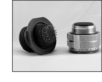
MIL-DTL-38999 Series II connectors
feature a bayonet coupling mechanism with lower profile
design and rear-removable crimp contact retention system.
These connectors were designed for military
and commercial applications where the prime requirements
are lower profile and lighter weight.
Reduction of both size and weight were
achieved through
the use of thinner shell walls and length restrictions.
These
design restrictions reduced the RFI attenuation characteristics
and the “scoop” protection, while yielding
an excellent general
purpose, lightweight connector. Compared to Series
I,
Series II connectors achieve up to 20% reduction in
mated
pair length, up to 39% reduction in outside diameter
and
up to 40% reduction in weight (128 pin mated pair).
This family of connectors is offered
in six receptacle-mounting
styles. They include square flange receptacles, for
both front
and rear panel (wall) mounting; square flange receptacles,
for both front and rear panel (box) mounting; square
flange
receptacle with extended grommet, for front of panel
(box)
mounting; and jam nut receptacles which incorporate
“ O” ring seals, designed for rear panel “D” hole mounting.
Plugs are available in two designs,
with and without RFI
grounding.
Fifty-two insert arrangement per MIL-STD-1560
are tooled
and qualified to MIL-DTL-38999 Series II, utilizing
3 to 128
M39029 contacts. Contacts come in sizes 22D, 22M, 22,
20,
16 and 12, terminating wire sizes from 28 to 12 gauge.
These connectors are available in wide
range of shell materials
and finishes. Aluminum shells are offered in electroless
nickel, bright cadmium, anodized, and olive drab cadmium.
Other finishes such as zinc cobalt are available upon
request
to commercial callouts only. In addition, we offer
passivated
stainless steel shells with standard environment-resisting
inserts (commercial callouts only).
|